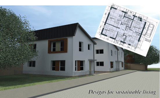
One day, all houses will be built this way

Factory fabricated panels consisting of welded wire trusses with an extruded polystyrene (EPS) core to which render produced at site is applied to each side. They have vertical, 100mm deep 2mm wire Warren trusses spaced at 50mm centres with pre-formed EPS strips between. The assembly is held together with 2mm horizontal wires on each face at 50mm centres welded to the truss chords.
The horizontal wires and vertical truss chords project approximately 9mm beyond each EPS face to permit wire to be anchored within the Portland cement or gypsum plaster finish applied to each face after assembly on the site.
The panels are manufactured in 1.2m width by 2.4m length. The nominal thickness of the panel wire frame is 100mm resulting in a finished wall thickness after plastering of 120mm or more.
Fire Resistant Wall General:Fire-resistant walls consist of the panels with an 80mm EPS core rendered with Portland cement plaster, lightweight Portland cement plaster and/or lightweight gypsum plaster.
Materials (conforming to British Standards)The panels will be designed in accordance with the applicable provisions of the British Standards Codes of Practice. The design loads cannot exceed set values, except where additional reinforcement is provided, and substantiated by calculations. The Avantgarde panel construction assembly may be used for free-standing walls when designed and anchored as cantilever walls. Panels are reinforced and tied at vertical joints to maintain alignment. Additional reinforcement and Portland cement plaster may be added as required by the design.
Wall Panels:Attachment to the slab and perimeter foundation is with 55mm long by 3mm thick steel holding down connector channels and 12mm diameter foundation bolts placed a maximum of 1.2m centres along width and at each panel end. Panel reinforcement and connector channels are attached with 30mm long, 12 gauge wires extending approximately 45 degrees upward along each panel face from each channel end. The upper end of the diagonal wires are attached to the panel reinforcement. As an alternate, shear receivers consisting of 55mm long channel-shaped 16 gauge sheet metal fastened with two clips or tie wires each side and anchored with 12mm diameter anchor bolts may be used with placement as above. These shear receivers may also be used at panel tops and door and window openings.
Panels are joined along vertical edges with strips of square welded wire mesh on each face centred on the panel joint. The mesh is attached to the vertical panel wire reinforcement with clips or tie wires spaced at 75mm centres at the edge wires and 35mm on centre at interior wire. Panels may also be joined on both sides with 2mm wire. In addition to the above butting panel edge wires are attached with the clips spaced at 70mm centres on each panel face. Corner and intersecting walls are connected with mesh trusses and clips or ties in a similar manner. Clips installed in accordance with figures when truss strips are used as joint mesh. Lintel sections over openings consist of panel sections with added truss reinforcement placed horizontally and reinforced.
Electrical conduits or wiring, switch boxes and outlet boxes may be installed prior to application of the Portland cement in accordance with local requirements. Outlet boxes are to be placed to minimise the cutting of the wire mesh reinforcement. Where two or more wires in the same direction are cut, they must be replaced with wire of the same gauge and attached with at least two clips at each end at a sufficient distance beyond the opening to develop continuity. Plumbing and waste pipes are limited to extending at right angles through the wall panels and located to minimise the cutting of panel wires.
Roof and Floor Panels:The standard panel and modified panel may be used for floor and roof panels.
Special Connection Device.Ledger Bolt: The bolt consists of a 12mm diameter British Standard J-shaped bolt with washers and nuts, and is fastened to the panel wires and plastered. The Portland cement plaster for the panel for use with this connection device must have a minimum of 28 day compressive strength of 1.50kg/cm2. The maximum allowable load is 250kg in tension and 350kg in shear.
Identification:The panel bundles are identified with a tag with the Avantgarde name and address and the product name.
Technical Assistance:Supplementary data and detailed information together with copies of relevant standard information, load test reports and reports of tests conducted in accordance with British Standards are available from Avantgarde Buiding Systems Ltd.
Thermal Performance:The buildings are designed to minimise thermal conductivity ie heat or cooling passing through the wall by using super low Lambda value insulation and minimising air leakage by completely sealing the building reducing passive solar gain through windows by utilising additional glazing and “K” reflective glass.
The U Value Calculation:20mm Portland cement render 280mm ESP 20mm Portland Cement Render 0.11w/m2k
Structural Calculation:Meets design standards for BS8110PG1 (1997) (3.4.4.4) (5.9.3.8.1.6) carried out by MET Consultancy Engineers to buildings up to 3 floors.
Foundations:Each individual house foundation is designed to cover for ground bearing pressure ranging from 25 to 250 KNM2 in accordance with British Standards.